


IMPORTANT: Do NOT connect the LED to any power source until the resistor is installed on the LED+ wire.
Powering the LED without the resistor in line can instantly fry the LED.
Exception: CR2032-style packs typically do not require a resistor.
For 9V, 18V, and 24V setups, use the correct resistor from the LED Voltage Guide.
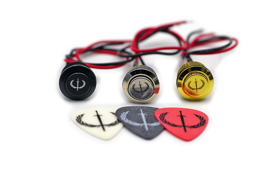
Thank you for choosing Iron Age killswitches. This page is your main installation hub, with a universal process overview, wiring diagrams, and trusted install videos.
Your killswitch wiring is consistent across most guitars because it connects to the output stage and universal jack points—not pickup brand-specific color codes. If you follow the sections in order and test before drilling, you’ll get a clean, reliable install without guessing.
Most installs can be completed in about 30–60 minutes depending on your guitar’s layout and whether you’re adding LED power components.
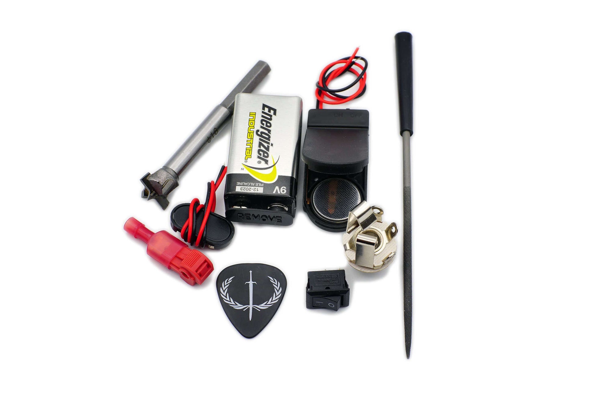
Recommended tools:
- 16mm Forstner drill bit
- Drill press or handheld drill
- Soldering iron (or solderless splices)
- Multimeter
- Alligator clips or temporary test leads
-
Needle rasp file (optional)
The mini switches do not require drilling & if you're installing one of our full-sized switches in place of a tone pot/knob, you can use a rasp file to enlarge the potentiometer hole if you don't wish to use a drill.

Table of Contents
Choose Your Path (Start Here)
If your switch has an LED, use the Mono or Stereo LED sections depending on your output jack and how you want the LED to behave.
-
Use Mono (LED) if you want manual LED control with an on/off switch.
-
Use Stereo (LED) if you want the LED to turn on automatically when you plug in a cable.
If you’re installing a Mini LED model, the wiring logic is the same as the standard LED sections—just without polarity markings on the back.
If your switch is Non-LED, jump straight to the non-LED section for the fastest install.
If you have active pickups (EMG/Fluence/etc.), this is still a jack-first install — treat the killswitch as a mute at the output stage.
Contents:
- Universal Quick Start (Process Overview)
- Wire layout for LED switches
- Kill Switch Installation For Mono Jack Guitars (LED)
- Kill-Switch Installation For Stereo Jack Guitars (LED)
- How To Install Mini LED Kill Switches
- Installation For Non-LED Switches
- Other Guitar Kill Switch Video Content
- Killswitch Resource Hub
Universal Quick Start (For All Guitars)
Your Iron Age killswitch installs the same way across most guitars because you’re wiring to universal output points — not specific color codes or pickup configurations.
You’re essentially working with two separate circuits:
-
Killswitch pair (mute) – no polarity
-
LED pair – polarity matters
Before drilling or soldering:
- Use temporary connections to confirm mute behavior before drilling or soldering.
- Wire the killswitch/mute circuit first, then the LED.
-
If you’re unsure which lug is tip/sleeve/ring, check your jack with a multimeter — some jacks are manufactured differently and the ring/aux contact can be swapped with the hot/lead lug.
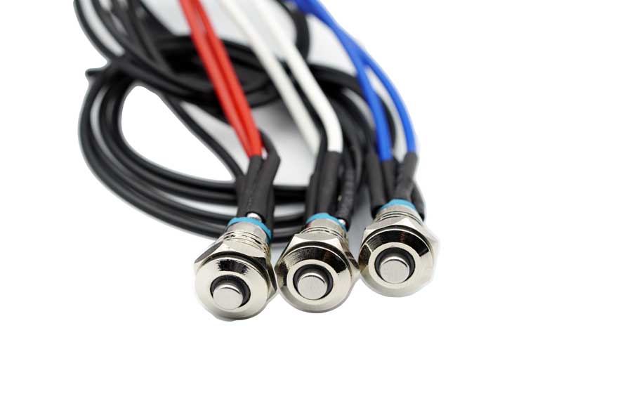
Wire Layout For LED Kill Switches
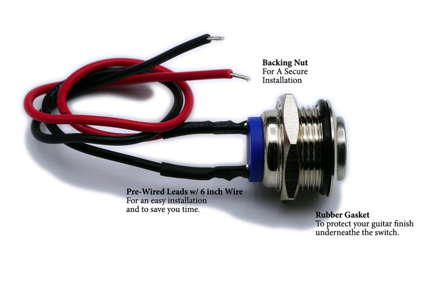
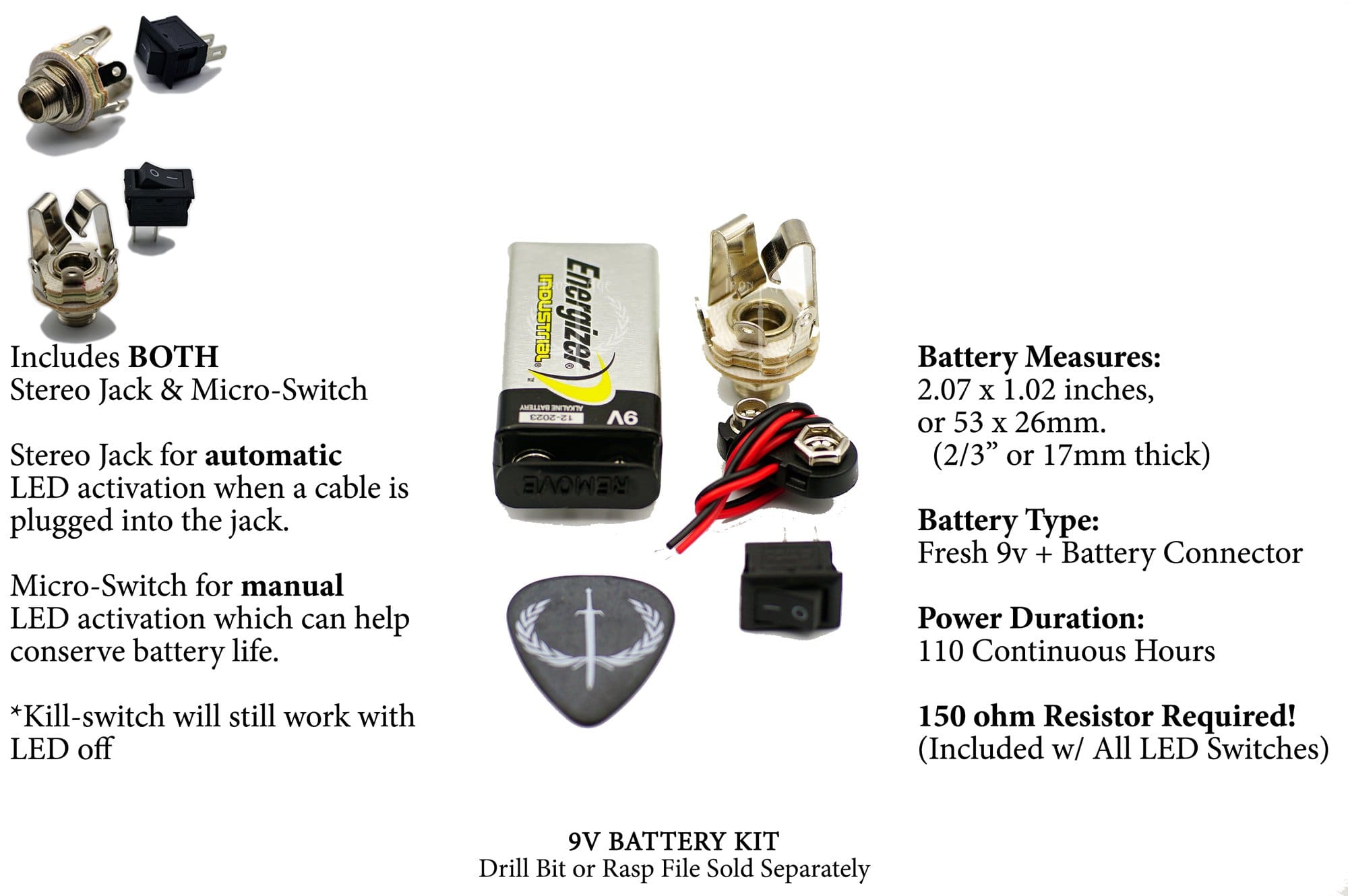
All Iron Age LED killswitches use two separate circuits: 2 LED wires and 2 killswitch wires. On full-sized 16mm models, the back of the switch marks LED + and LED – to identify the LED terminals; the other two wires are the killswitch pair with no polarity.
Older switches had an LED color indicator dot, and newer batches may not — the + / – markings are the consistent reference on both versions (see the two photos). Mini LED switches don’t have polarity markings, so you choose one LED wire as LED+ and place the resistor on that wire.


Kill Switch Installation For Mono Jack Guitars
With a mono output jack, the LED won’t automatically turn on/off with your cable. That means you’ll need an additional on/off switch for the LED, otherwise it would stay on any time it has power.
This is a great option if you want manual LED control and better battery conservation. The LED and killswitch are separate circuits, so the killswitch will still function normally even if you leave the LED power off.
For LED power in this setup, you can use:
-
9V battery with the correct inline resistor, or
-
CR2032-style pack, which is slimmer and typically does not require a resistor
Both options offer similar real-world longevity. If you want the LED to turn on automatically whenever you plug in a cable, use the Stereo Jack configuration instead.
Diagram:

Videos:
Below are two walkthroughs showing this configuration.
-
Our older Iron Age video shows the same wiring method, but it uses an older resistor setup. Back then we used two smaller 75Ω resistors; now we include a single higher-wattage 150Ω resistor for better heat dissipation (the newer resistors may be larger and can be grey or blue).
-
The second video was made by Mark from Guitar Guts, who does excellent guitar mods and custom work. You can find him on YouTube at GuitarGuts.tv and on Instagram @GuitarGuts.
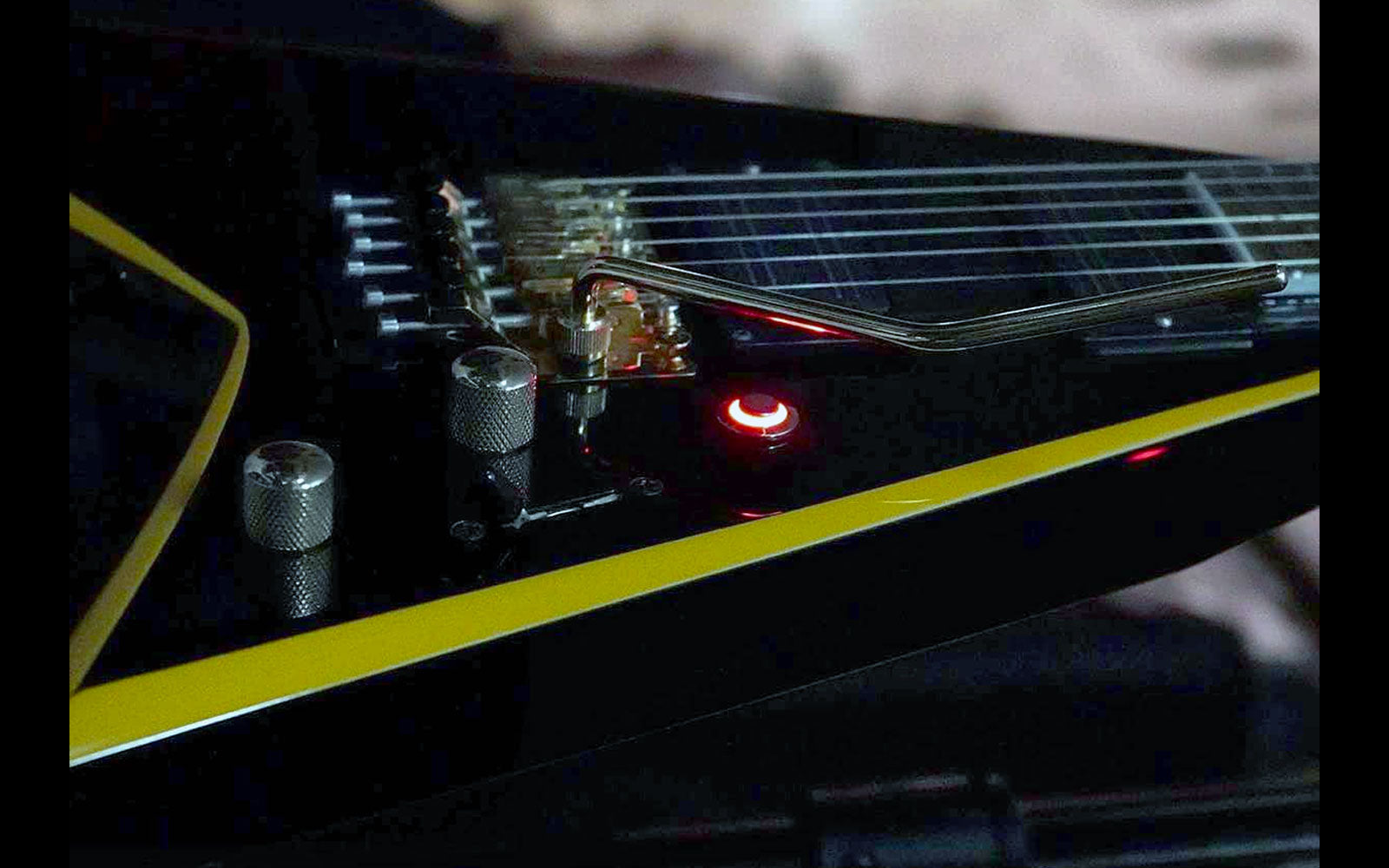
Kill-Switch Installation For Stereo Jack Guitars
This is the most common LED setup for guitars that already have a stereo output jack, which is typical for guitars with active pickups or preamps. In this configuration, the LED will turn on automatically when you plug in a cable.
If your guitar already has a battery installed, you can usually use that same power source to run the LED for your Iron Age switch. If you’re building a fresh setup, you can add a 9V or CR2032 power option and tuck it into the electronics cavity without routing a new compartment.
Diagram:

[Click diagrams to expand in a new tab]
Video:
The walkthrough below uses this same configuration.
This video was made by Colin from CS Guitars in Scotland (Science of Loud) in Scotland. You can find more of his work on YouTube at The Science Of Loud or through CS Guitars.
How To Install Mini LED Kill Switches
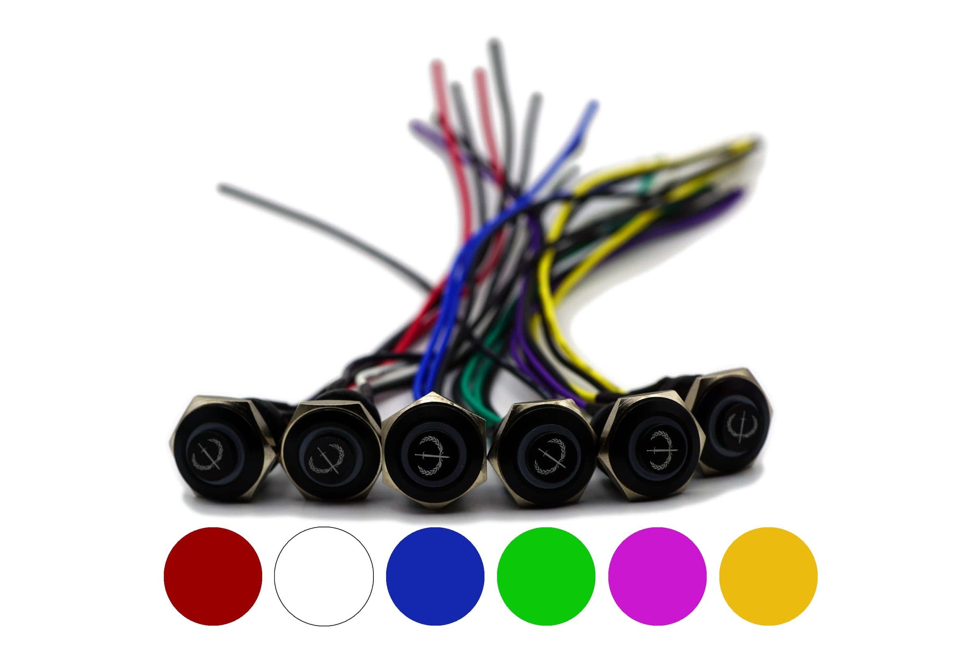
Mini LED models use the same two wiring approaches above (Mono or Stereo). The only real difference is that the mini switch doesn’t have room on the back for LED + / – markings.
Use this simple layout:
-
Black pair = killswitch (mute) wires
-
White/colored pair = LED wires
For the LED on a mini switch, choose one of the two LED wires as LED+ and attach the resistor to that wire. The remaining LED wire becomes LED–.
You can power the LED with a 9V battery as long as the resistor is on LED+, or use a CR2032-style pack, which does not require a resistor.
If you don’t want the LED at all, you can leave the LED wires unplugged — the killswitch function will still work normally.

Installation For Non-LED Switches
(Both Mono & Stereo Jacks)
Non-LED models are the simplest Iron Age switches to install. They work with either a mono or stereo output jack and only require two wire connections, so this is often a 10–15 minute job.
The two killswitch wires have no polarity. Connect:
-
One wire to tip/hot
-
One wire to sleeve/ground
If the switch seems to work backwards (signal only passes while pressed), it was wired in the opposite configuration. Rewire it to match the diagram below, or wire the killswitch in parallel at the jack rather than in series.
Optional alternate method:
You can also install a non-LED killswitch at a volume pot by using the back of the pot as ground and the appropriate signal lead as hot. The jack method is the most universal and easiest to verify.
Diagram:

[Click diagrams to expand in a new tab]
Videos:
Below are two quick walkthroughs of non-LED installation:
-
The first video is presented by Charles Caswell of Berried Alive, who we collaborated with on a limited-run killswitch in the past.
-
The second video features Derek from Big D Guitars. You can find his YouTube channel at BigDGuitars.
Other Guitar Kill Switch Video Content
If you want to see Iron Age killswitches in real-world builds and demos, these videos are great quick references. They’re not required for installation, but they’re helpful for seeing how different players and creators use the switch in context.
Guns & Guitars – A custom Les Paul build walkthrough that features an Iron Age LED killswitch in the finished setup.
Nick Olivera – A clean demo of what a killswitch can do musically, with a performance clip that highlights the effect in use.
Bruno Freitas – A straightforward killswitch demonstration and review.
Killswitch Resource Hub
If you’re bouncing between installs, troubleshooting, and LED power options, this quick hub keeps everything connected in one place.
| Resource | What you’ll find there |
|---|---|
| Shop Kill-Switches | Current Iron Age models, options, and ordering info. |
| How To Install | Your core install page for standard wiring and installation videos. |
| F.A.Q. #1 | Most common install questions and fast fixes. |
| F.A.Q. #2 | Less common scenarios, compatibility notes, and deeper troubleshooting. |
| EMG/Fluence Install | The universal, beginner-friendly “jack-first” guide for active pickup anxiety. |
| LED Voltage Guide | Full resistor/voltage breakdown for 9V, 18V, 24V, and more. |
| Killswitch Basics | A simple overview of what a killswitch is, what it does, and how players use it. |
Last Updated: Dec 10, 2025